| Model |
OKO-22M-UT |
Parameter |
Value |
PULSER |
Pulse mode |
Spike pulser, Square-Wave pulser |
Pulse Voltage (SQ mode) |
120-300 V in steps 10 V with tolerance 10% |
Pulse falling/rising time |
5 ns |
Pulse Width (SQ mode) |
20 – 500 ns in steps 10 ns with tolerance 10% |
PRF (SQ mode) |
15 – 2000 Hz in steps 5 Hz, 3 automatic modes: Auto Low, Auto Med, Auto High, Manual |
Pulse Voltage (spike mode) |
Low (100 V), High (400 V) |
Pulse energy (spike mode) |
Low (30 ns), High (100 ns) |
PRF (spike mode) |
15 – 8000 Hz in steps 5 Hz, 3 automatic adjustment modes: Auto Low, Auto Med, Auto High, Manual |
Damping |
50Ω, 62Ω, 150Ω, 400Ω |
| |
RECEIVER |
Gain |
0 to 110 dB adjustable in steps of 0.2, 0.5, 1, 2 dB |
Receiver input impedance |
400Ω±5% |
Receiver bandwidth |
0.2-27 MHz (- 3 dB) |
Digital filter setting |
Eight digital filter sets standard (0.2-10 MHz; 2.0-21.5 MHz; 8.0-26.5 MHz; 0.5-4 MHz;
5-15 MHz; 5-15 MHz; DC-10 MHz ) |
Rectification |
Fullwave, positive halfwave, negative halfwave, RF |
Amplitude measurement |
0-110% |
Reject |
0-80% FSH |
Units |
Millimeters, inch or microseconds |
Range |
1 to 6000 mm |
Velocity range |
1000 to 10000 m/s in steps of 1, 10, 100, 1000 m/s |
Thickness measurements range |
0.6 to 6000 mm |
Probe angle |
00 to 900 in steps 0.10, 1.00, 100 |
| |
DIGITAL SPECIFICATION |
ADC |
10 – bits with the sampling rate 100 MHz |
A-Scan buffer |
8 KB |
| |
GATE |
Measurements gates |
- 2 fully independent three-level gates for amplitude and time of flight measurement.
- Additional gate for acoustic coupling control.
- Additional gate for immersion control.
- Special-purpose gate of the Automatic gain control (AGC).
|
Start Gate |
Variable over entire range |
Width Gate |
Variable over entire range |
Gate height |
Variable from 2 to 100% FSH |
| |
MEASUREMENT SPECIFICATION |
Result display |
A-scan, B-scan, C-scan, D-scan, TOFD scan |
DAC/TCG |
- Dynamic range is up to 110 dB.
- Number of points is 32.
- Building TCG curve by DAC
|
DGS |
- Automatic building of up to 3 curves for different equivalent diameters
- Calibration at calibration blocks and testing objects
- Building TCG curve by DGS
|
| |
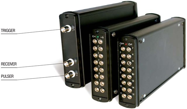
CONNECTORS |
Probe connector |
2 BNC or 2 Lemo 1S |
USB port |
USB-2.0 |
Ethernet |
+ |
Alarm output |
+ |
Encoder |
1 Lemo (with the option of two encoders operation) |