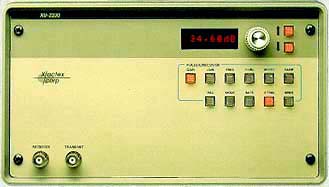
| XU-2200 시리즈는 시스템용 하이 스피드 초음파
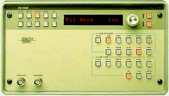
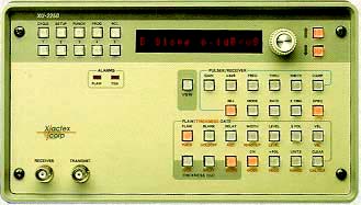
탐상기이다. XU-2230은 첨단 pulser/receiver 이며 XU-2240은 증폭 알람 게이트와 전면 패널에서 세팅 값을 저장하는 기능을 가지고 있다. XU-2250은 XU-2240에 더하여 두께 측정 기능을 가지고 있다. 최첨단 기능을 사용한 XU-2200 시리즈는 자동화 초음파 검사 시스템에 적합한 첨단 탐상기이다. XU-2200 시리즈는 고분해능, 깊은 침투력 및 고감도를 필요로 하는 곳에 적합한 기기이다. 기기에 내장되어 있는 RS-485 시리얼 링크는 1000 m 거리까지 초당250,000 비트의 데이터를 주고 받을 수 있다. |
|
pulser receiver serial computer interfaces |
|
alarm gate wave pulser resolution receiver RS-485 serial computer interfaces |
|
|
and alarm gate and thickness gauge base gain of instrument allows high speeds testing 485 serial computer interfaces delay and new thin wall mode |
| 주요 사양 Pulser Type.................................................................... Switchable Spike/Square Amplitude.................................................................. 300volts into 50ohms Damping................. Selectable 30, 34, 40, 50, 70, 100, 200, 1 kohms Receiver Tuned Frequencies..................................................... 1, 2.25, 5, 10, 15 MHz Wideband Bandwidths......................................... 1-20, 3-20, 5-20, 5-30 MHz Gain.............................................. Adjustable -28 to +81.8dB in .05dB steps Display Presentation..................................................... RF, +, -, ±, Hi Res± Reject..................................................... Linear reject adjustable 0-80% f.s Mode........................................................ Pulse/Echo, Pitch/Catch (THRU) Amplitude Gate (XU-2240,XU-2250) Modes............................................................................. Normal, Interface Blanking Interval..................................................... Adjustable .05-1000 μsec Delay,Gate Interval.................................................. Adjustable .05-1000 μsec Alarm Polarity..................................................................... Selectable Hi/Lo Alarm Level................................................................ Adjustable 0-100% f.s. Detector Output.............................................. 0-10 volts analog, 8bits digital Cyclic Operation............................... Allows up to 16 separate gate positions Thickness Gate (XU-2250) Modes........................Selectable contact, delay line (immersion) or thin wall Ranges.................................................. Selectable .01" to 1", .1"to 10" Display(LED readout)...................................................... 3 digits, .999, 9.99 Signal Conditioning..................................................... Adjustable AGC,DGC Thickness Output......................................... 0-10volts analog, 10bits digital Resolution........................................................................................10bits Alarms............................................. Hi, Lo & No-Test(TTL level compatible) Computer Interface RS-232 Serial, RS-485 High Speed Serial Command Link, RS-485 High Speed Serial Data Link, lsolated Parallel |
 |
|
XU-2200 시리즈의 브로셔를 인쇄하고자 하실 |
| 경우 이 아이콘을 클릭한 후 프린트하십시오. | ||
![]()
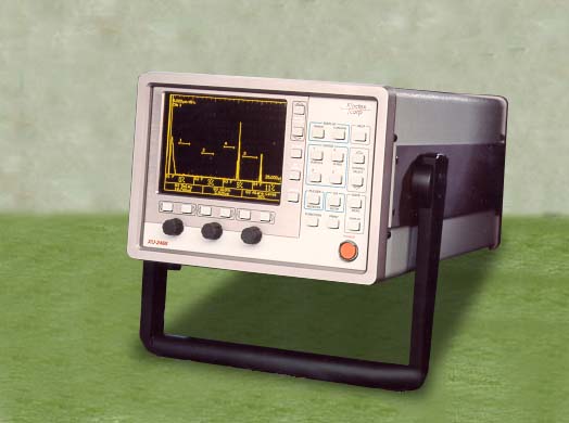
Features of the XU-2468:
· Large EL display
· Fast and easy Test Setup
- Direct access keys and three quick knobs allow immediate changes of
multiple functions.
· On Line Help
makes manual nearly obsolete.
· Digital Single Shot Peak Detection
can accurately detect & measure a flaw each rep, at a rep rate of 24 kHz.
The XU-2468 is an eight channel flaw detector and thickness gauge incorporating an
electroluminescent waveform display panel. Its high-speed systems capability, coupled with
its user-friendly design make the XU-2488 the best choice.
The XU-2468 is ideally suited for high-speed systems application. Digital Single Shot Peak
Detection enables the instrument to detect and measure a flaw in one rep. This, combined
with a rep rate of 24 kHz, results in unparalleled high-speed testing.
Four gates are incorporated into the XU-2468 to provide unmatched flexibility and economy.
Flaw detection, thickness detection, surface following, back following and back echo
attenuation capability are all provided
Each channel can be individually set to operate as a flaw detector or thickness gauge. If
a channel is set to flaw detect then Gates 1-4 can be enabled as flaw detectors. If a
channel is set to thickness detect then Gate 4 is a Hi-Res thickness gauge with a
resolution of ±.0001". Gate 1 can always be used as a surface detector for any gate
set to surface follow.
The large 4.5 × 3.4 display screen provides an uncluttered view of the waveform. Four
measurements and three Quick Knob functions are visible without interrupting the waveform
display. A pop-upcursor enables quick setup of ultrasonic tests and provides measurements
of tests and provides measurements of both thickness and amplitude.
All Xactex keys and functions are straightforward and indicated with clear, concise
text-no confusing graphics. Large, legible characters are used for all measurements and
instrument settings.
Testing can begin quickly with the XU-2468, Direct Access Key (such as PULSER/RECEIVER,
GATE1-4 and RANGE) require only a single key stroke for immediate adjustment of multiple
instrument functions using the three Quick Knobs.
Once a Direct Access Key is pressed, the most commonly adjusted functions appear above the
three Quick Knobs and a pop up Function Menu appears in the upper right hand corner. The
left and middle Quick Knob are reserved for controls which are frequently changed. You can
select any control from the Function Menu and adjust it with the right Quick Knob using
the Menu Select Keys. The pop up menu disappears at the touch of a key, so your waveform
display remains uncluttered.
A user-defined Key, MY MENU, can be set up by the operator to access the three functions
most often used in a test.
If you have any questions you do not need to search for your manual. Press the Help key
and a pop up window immediately displays a description of the function you are adjusting.
The advanced design and performance of the XU-2468 provides high-speed testing without
complicated setup procedures. So you can concentrate on your testing... not an instruction
manual.
Direct Access Keys
PULSER/RECEIVER..........allows access to all P/R functions, including GAIN,
REP RATE, REJECT, DAMP.
GATE 1-4........................individual access to all gate positions and flaw and
thickness gate functions, including Alarm Level,
Back Following Gate, Qualifiers.
RANGE............................controls horizontal range functions, such as
RANGE, DELAY, VELOCITY.
MY MENU........................user-defined key to access the three most
frequently-used functions in a test.
FUNCTION.......................accesses advanced instrument setups, such as I/O,
DATA LOGGER, Buzzer.
CURSORS.......................allows quick Amplitude/Thickness measurements,
without positioning the Gate.
CH SETUP.......................allows quick setup of the selected channel to
operate as a flaw detector or thickness gauge.
SPECIAL KEYS
CHANNEL SELECT........selects the channel of interest to display or calibrate.
SAVE MEAS......................immediately saves a Thickness and /or Amplitude
measurement.
SAVE WAVEFORM............................immediately saves displayed waveform.
PRINT.......................prints either the displayed waveform or the data logger
measurements.
FREEZE...................freezes the displayed waveform for analysis or printing.
LOCK.....................locks front panel controls to prevent inadvertent changes
to settings during a test.
Additional Features
A split screen allows the A-Scan and a magnified section of the A-Scan to be displayed
simultaneously.
Memory can store up to 300 waveforms and 30 setups.
Amplitude and thickness measurements are made each rep.
Physical Specifications
Dimensions................................................................ 9 1/8"W
× 6 5/8"H × 16"D
Weight....................................................................... 15 lbs
Operating Temperature................................................ 0℃ to 55℃
Power........................................................................
100 W
Display Specifications
Size......................................................... 4.5" ×
3.4"
Type........................................................ flat panel
electroluminescent(EL)
Update Rate............................................. 60 Hz
Viewing angle........................................... 160°
Pulser Specifications
Rep Rate................................................ 100 Hz to 24 kHZ, in 100 Hz steps
Damping................................................. selectable, 50, Hi.
Pulse Width............................................ adjustable, 30-650
ns
Amplitude............................................... 300V into 50
Receiver Specifications
Pre-Amp Gain........................................ adjustable, -30dB to in 0.1dB steps
Common Gain........................................ selectable, 0-80dB in 10dB steps.
Turned Frequencies................................ 1, 2.25, 5.0 ,10.0, 15.0
Wideband Bandwidths............................. 1-20, 3-20, 5-20, 5-20 MHz
Waveform Display................................... switchable; RF, Detected RF
(+,-,±,
Hi Res ±), Time-of-Flight
(TOF),
and Echo Blanking.
Data Logger Specifications
2500 measurement readings total (Thickness and/or Amplitude). Up to 99 files may be stored
to print or review.
Input /Output Specifications
Command Link................................. RS-232, 9.6 k Baud or RS-485,
1 M Baud
Data Link........................... RS-485, 1 M Baud 20 bit Thickness, 8 bit Amplitude.
Analog Output............... up to 4 provided. An output can be assigned to any
combination
of 4 measurements (Flaw or Thickness)
Alarms......................................... selectable Hi/Lo for each Thickness Gate;
TTL alarm for each Amplitude Gate.
Parallel Port................ generate hard copies of waveform or data on a printer.
Accessories
NDT Silver..................... Windows 95/NT based software with instrument control,
strip charts, alarms, and reports.
 |
|
XU-2468의 브로셔를 인쇄하고자 하실 |
| 경우 이 아이콘을 클릭한 후 프린트하십시오. | ||
 |
|
NDT Silver의 브로셔를 인쇄하고자 하실 |
| 경우 이 아이콘을 클릭한 후 프린트하십시오. | ||
|
|
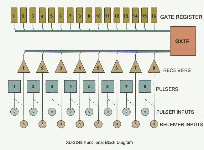
| Eight-Channel
Multiplexed Flaw Detector The XU-2248 can on any rep : Fire any one of 8 pulsers Listen with any one of 8 receivers Store the result in any of 16 gates High speed RS-485 serial links give fast, reliable data/control from external controller Integral multiplexer improves system performance |
|
The XU-2248 is an 8-channel multiplexed ultrasonic flaw detector. It uses the newest technology for the 8 pulsers, 8 receivers and 16 gate channels incorporated into the XU-2248. The many interfacing options available to an ultrasonic system developer permit the XU-2248 to be integrated into the virtually any computer-controlled test system. A variety of data reduction algorithms, incorporated into the XU-2248, substantially reduce the data that must be transmitted to the system controller. They also reduce the system overhead. |
|
| The XU-2248 provides an improved, coat-effective alternative
for for multiplexed systems. Traditionally, a multiplexed system "patches" together an external multiplexer and a conventional flaw detector and the multiplexer are often not well matched. Since an external multiplexer replaces the most important part of the flaw detector, it may compromise the system performance of an otherwise good flaw detector. |
|
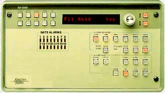
| Front panel controls on the XU-2248 allow for a very wide
range of applications in ultrasonic test systems. The Damping and width of each pulser are individually adjustable, and the operator can choose pulse-echo or pitch-catch operation for each pulser, as well. The rep rate is adjustable from 100 Hz - 10 kHz and is shared among all of the channels. |
|
| The Gains of each receiver amplifier are fully adjustable,
individually. In addition, a common Gain control provides for rapid adjustment of all of the channels together, as does Reject and Frequency. Tying two receiver inputs together provides separately (the example system uses this idea to get separate gains for pulse-echo and pitch-catch operation). The XU-2248 output is monitored by an external oscilloscope. |
|
| The 16 gate channels each have a separate Alarm Output and
Peak Detector. Alarm LED's on the front panel give a visual alarm indication. The peak detected output from any gate channel (selected from the front panel) can be applied to the Analog Output on the rear panel. All of the peak detector outputs are available to a system controller over the high speed serial link. Alarm Filters for each of the gate channels are separately adjustable and allow the XU-2248 to be used in noisy industrial environments without generating spurious alarm indications that would slow system test throughput. |
|
| In addition to these individual gate controls, the XU-2248
allows a gate to be re-positioned on every rep. These gate controls include Blanking, Delay, Width and Alarm Level. Thus, the reps assigned to be a particular Gate Channel may have many gate positions and Alarm Levels. |
|
| Flexible triggering controls permit the operator to trigger
an external oscilloscope on (and thus View) any individual rep, when any
particular pulser fires, when any particular receiver "listens", or when any particular gate channel is used. The operator can also program the XU-2248 to trigger on an arbitrary group of reps. |
|
| Using the concept of cyclic operation, pioneered by
Xactex
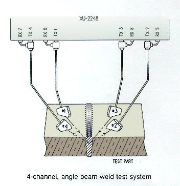
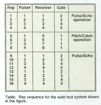
in the XU-2248 Flaw Detector, the XU-2248 can generate complex, cyclic test sequences. These test sequences can be programmed from the instrument front panel or input from an external IBM -compatible PC, using the UT-QWIK software supplied with the XU-2248. On any given Rep in the cyclic sequence, the XU-2248 can fire any one of the 8 pulsers, "listen" with any one of the 8 receiver amplifiers, and apply the results to any one of the 16 gate channels. One possible sequence is illustrated for a common weld test system by the accompanying Figure and Table. |
|
| This system uses two parts of transducers. Each transducer in a pair is "aimed" at its mate, making pulse-echo and pitch-catch operation possible. The inputs of two receivers are tied together, which allows separately adjustable gains for pulse-echo and pitch-catch operation. Referring to the table, which displays the programming of the rep sequence, the first four reps are pulse-echo tests involving all four transducers. The next four reps execute a pitch-catch test between transducer pairs to check coupling. Note that the "results" of the coupling check are all applied to Gate 1, though they could be applied to four additional gates, if desired. Reps 9-12 and 13-16 are repeats of reps 1-4. This Table illustrates a 16-rep sequence that will repeat during the next 16 reps and continue repeating as the test progresses. Sequences up to 128 reps can be programmed, stored and recalled by the XU-2248. |
|
|
|
| SPECIFICATIONS |
|
| PULSERS - 8 separate pulsers are provided. One pulser may be triggered on each rep. | |
| Common Pulser Controls Specifications and Outputs | |
| Type | Square wave |
| Amplitude | 300 Volts into 50 Ω |
| Rep Rate | 100 Hz to 10 kHz in 100 Hz steps |
| Rise Time | Less than 15 ns |
| Individual Controls | |
| Damping | Selectable, 50 Ω or 1 kΩ |
| Pulse Width | Adjustable 30 - 650 ns |
| Mode | Switchable pulse-echo or pitch-catch |
| RECEIVER - 8 separate receiver amplifiers are provided. One receiver may " listen" on each rep. |
| Common Receiver Controls, Specifications and Outputs | |
| Tuned Frequencies | 1, 2.25, 5, 10, 15 MHz |
| Wideband Bandwidths |
1-20, 3-20, 5-20, 5-20 MHz |
| Gain | Adjustable -30 to +80.0 dB in 0.1 dB steps |
| Display Output | Switchable RF, Detected RF |
| Detected RF Presentation |
+, -, ±, Hi Res ± |
| Reject | Linear reject adjustable 0-80% f.s. |
| Individual Controls | |
| Gain | Adjustable 0 to 60 dB below common gain in 0.1 dB steps |
| Equivalent Input Noise |
25 μvolts rms, wideband |
| Channel Isolation | 60 dB or better |
| AMPLITUDE GATE |
| 16 separate gate channels are provided. The results of any rep (peak detected output and alarm condition) may be applied to any of the 16 gate channels. |
| Common Gate Controls, Specifications and Outputs | |
| On | Toggles all the gates on or off |
| Velocity | Used to generate gate position readings, adjustable from 0.05 to 0.3 inches/μsec. |
| Detector Output Hold |
Selectable 0 - 1000 milliseconds or reps |
| Alarm Output Hold | Selectable 0 - 1000 milliseconds or reps & external clear |
| Individual Gate Controls | |
| Alarm Noise Filter | Adjustable 1 - 15 |
| Alarm Polarity | Selectable Hi/Lo |
| Mode | Selectable, Normal or Interface gate with adjustable blanking |
| Detector Output | 10 volts analog, 8 bits digital |
| Alarm Outputs | TTL level compatible, "Hi" on alarm & no-test |
| Alarm Indicators | Visual and audible |
| Cyclic Rep Controls Adjustable for each rep individually | |
| Blanking Interval | Adjustable .05 - 1000 μsec. (.006 - 112 inches steel) |
| Delay Interval | Adjustable .05 - 1000 μsec. (.006 - 112 inches steel) |
| Gate Interval | Adjustable .05 - 1000 μsec. (.006 - 112 inches steel) |
| Alarm Level | Adjustable 0 - 100% |
| COMPUTER INTERFACE |
| RS-232 Serial | 9.6 kBaud, Allows software control of the functions
and cyclic operation of a single XU-2248 |
| RS-485 High Speed Serial (2 channels) Command Link |
Selectable 9.6, 62.5, 100, 250 kBaud, Allows control
of the functions, cyclic operation and high speed data acquisition for single or multiple 2200 Series instrument. |
| COMPUTER INTERFACE (cont.) |
| Data Link | Gate Amplitude. 1 MBaud transmission rate with external synchronous data clock. Allows high speed data acquisition on each rep. Optimized for use with the Xactex XT-3032 RS-485 Serial Interface Board. |
| Isolated Parallel | Outputs parallel 8-bit data |
| Software | IBM PC compatible, MS DOS 3.1 or higher. Included is
"UTQWIK", a program that allows operation of the instrument over the serial links from a PC. The program also provides for storage and recall of instrument setups on disk. A Microsoft C compatible "object file" is also included. This "driver" supplies all the command codes for the XU-2248 and simplifies embedding UT instrument control and data acquisition within user-generated custom software. |
| POWER |
| AC Input | 85-264 VAC, 47 to 63 Hz |
| Power Consumption | 60 Watts |
| PHYSICAL |
| Size | Nominally 10 1/4" (W) x 7 3/4" (H) x 16 1/2" (D) |
| Size (1/2 rack unit) | Nominally 9" (W) x 7 1/4" (H) x 16 (D) |
| Weight | Less than 22 lbs |
| Weight (1/2 rack unit) | Less than 15 lbs |
| 관련 제품들 |
 |
|
 |
 |